


Electrical energy components: a complete guide
Electrical energy: essential concepts
Harnessing electricity has been one of the most revolutionary technological achievements in history, transforming industry and dramatically improving quality of life. Since its discovery, technological and social progress has accelerated at an extraordinary pace. But how familiar are you with the concepts behind electrical energy? This guide explains the essential terms you need to understand how electricity works, from generation through to the point where it reaches consumers.
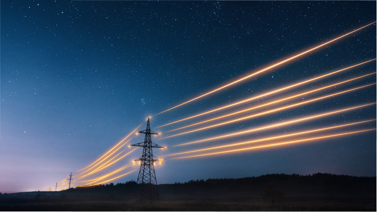
How much do you know about electricity? This form of energy, produced by the movement of electrically charged particles such as electrons through a conductor, involves a wide range of concepts and components. To help you understand how it works, along with the electrical quantities and components needed to use electricity safely and efficiently, we've explained the most important electrical terms you should know.
Electrical quantities
Electricity is defined by several electrical quantities that help us measure and understand how electrical and electronic systems work. From the point where electricity is generated to the moment you switch on a light at home, these quantities describe how electricity behaves at every stage and how it interacts with the components connected to the system.
-

Voltage (Volts)
Voltage measures the difference in electrical potential between two points and is expressed in volts (V). It is also commonly referred to as electrical tension – which may be classified as high, medium or low voltage – or simply as potential difference.
To understand the concept, imagine a standard 1.5 V battery. The negative terminal (-) is full of electrons eager to move, while the positive terminal (+) attracts them. The 1.5 volts do not represent the amount of energy stored in the battery, but rather the force that pushes the electrons from the negative terminal to the positive one.
When the two terminals are connected by a wire, this force is released and the electrons flow towards the positive terminal, creating the electric current that powers devices such as a torch.
-

Current (Amperes)
If voltage refers to the force that pushes electrons from one terminal to another, electric current measures how much charge actually flows. In other words, it is the amount of charged particles – electrons or ions – moving through a conductor.
Imagine water flowing through a pipe. The water represents the charged particles travelling from one point to another. In this analogy, the current is equivalent to the flow rate of the water. Electric current is measured in amperes (A), named after the French physicist André-Marie Ampère.
As these charged particles move, they generate a magnetic field around the conductor. This phenomenon is the principle behind devices such as electromagnets.
-

Resistance (Ohms)
As its name suggests, electrical resistance is the opposition that electric current encounters as it flows through a conductor. In the International System of Units (SI), resistance is measured in ohms (Ω), represented by the Greek letter omega.
Returning to the water-pipe analogy, resistance is similar to narrowing the pipe. The restriction reduces both the amount of water that can flow and the force with which it travels, just as electrical resistance limits the flow of current.
-

Contracted power (kilowatts)
Contracted power is the maximum amount of electrical power that a customer can use simultaneously in their installation, as specified in their electricity supply contract. It is measured in kilowatts (kW).
-

Energy consumption (kilowatt-hours)
Energy consumption refers to the total amount of electricity used while an electrical appliance is operating. For example, it is the energy consumed while your washing machine completes a full wash cycle. Because it depends on both power and time, it is measured in kilowatt-hours (kWh).


How does electricity work?
Voltage, current and resistance: the three forces that power your electrical devices.
-
Unit What is it? In practice
Volt (V)
The electrical force, or voltage, that pushes electrons from the negative (-) terminal towards the positive (+) terminal.
A 1.5 V battery doesn’t indicate the amount of stored energy – it indicates the attractive force between its terminals. When a wire is connected, electrons flow towards the positive terminal, creating an electric current.
-
Unit What is it? Interesting fact (Magnetic effect)
Ampere (A)
The amount of electric charge (electrons) flowing through a conductor over a given period of time – the electrical equivalent of water flow.
Moving electric charges generate a magnetic field around them, a principle that makes electric motors and electromagnets possible.
-
Unit What is it? In practice
Ohm (Ω)
The opposition that electric current encounters as it passes through a material.
Materials such as copper offer very little resistance, making them excellent conductors. Plastics and rubber, by contrast, have very high resistance, making them effective electrical insulators that greatly reduce the flow of current.

Fundamental electrical laws
To better understand how the main electrical quantities are related, it is important to understand two fundamental laws that govern electricity: Ohm's Law and Joule's Law.
Ohm's Law
This law, formulated by German physicist and mathematician Georg Simon Ohm, is used to determine the relationship between voltage (V), current (I) and resistance (R) in an electrical circuit.
It is expressed through the formula V = R · I. It can also be rearranged to calculate current, in which case the formula becomes I = V/R.
In practice, this formula explains how electrons behave when travelling through a cable:
- The higher the voltage, the higher the current. If resistance (R) remains constant and voltage (V) increases, more electrons will flow through the conductor, meaning the current (I) will also increase. Returning to the water analogy, this is similar to increasing the amount of water flowing through a pipe.
- The higher the resistance, the lower the current. Conversely, if resistance (R) increases while voltage (V) remains the same, the electric current will decrease. Using the same water analogy, this would be like squeezing a hose while water is flowing through it. The pressure applied to the hose creates resistance, reducing the amount of water that can pass through.
Joule's Law
Formulated by physicist James Prescott Joule, this law explains a very common everyday phenomenon: why electrical devices heat up when they are operating. In simple terms, when electric current passes through a cable or circuit, electrons constantly collide and interact with the atoms in the conductive material. This friction generates kinetic energy that is released as thermal energy (heat).
The Joule effect appears in many everyday applications:
- In appliances and electrical devices: its application allows everyday products such as toasters, hair dryers and ceramic hobs to operate by making use of this phenomenon.
- As a safety measure: in electrical installations, this principle is considered when installing fuses. These devices interrupt the flow of electricity when the temperature exceeds a predefined safety limit.
- However, it can also present risks: the Joule effect explains why a plug may overheat or why an electrical short circuit can develop into an accidental fire. Understanding its effects and monitoring the temperature of electrical devices during use can help prevent accidents.
Electrical and safety system components
When you arrive home and switch on the lights, this simple everyday action relies on a complex electrical installation that delivers energy safely for use. These are the key components you should know about:
Main distribution panel
The main distribution panel in a home or building centralises all the control and safety mechanisms that distribute the electricity entering the property. It is also commonly known as the electrical panel or breaker panel. It contains the circuit breakers and the residual current device (RCD), which regulate the flow of electricity to the different parts of the installation.
Residual current device (RCD)
The main function of the residual current device (RCD) is to detect electrical faults or current leaks and interrupt the electricity supply when necessary.
Circuit breaker
Miniature circuit breakers (MCBs), also known as thermal-magnetic circuit breakers, are located inside the main distribution panel and control the electricity supplied to different circuits in a home or to specific electrical appliances. The main distribution panel must contain at least five of these circuit breakers per residual current device, and the maximum number depends on the number of circuits installed in the building. These circuits may correspond to specific appliances (such as refrigerators, washing machines or ceramic hobs) or different areas of a home (such as lighting, bathrooms or kitchens).
Circuit breakers are selected according to the amperage required to protect each circuit. For example, they may range from 10 A for lighting circuits to 16 A or 25 A for electrical appliances requiring greater power.
Electrical safety at home:
key principles
Electrical safety in the home depends on a range of devices and best practices that work together to protect both people and equipment. Although many of these elements go unnoticed, understanding their function helps identify potential risks and keep an installation in good condition.
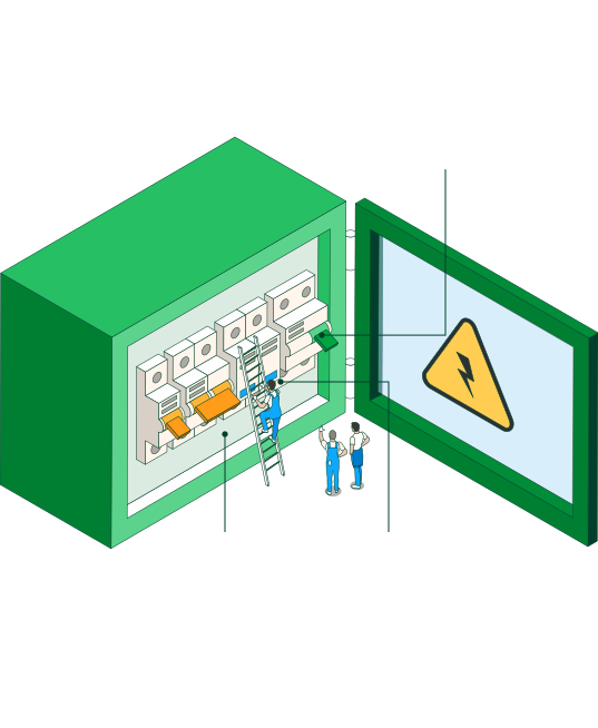
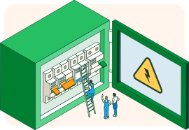
How to identify the electrical panel
The electrical panel (consumer unit) is the central point of a home’s installation. It houses the main protection and control devices.
-
RCD (Residual current device)
Detects current leakage and protects against indirect contact.
-
Circuit breaker
Protects the installation against overloads and short circuits by cutting off the current when a safety limit is exceeded.
-
SPD (Surge protection device)
Protects against voltage spikes that may damage electrical equipment.
1 of 3
Residual current device (RCD)
-
How is it tested?
It includes a “TEST” button that simulates a leak. When pressed, the device should trip immediately. It is recommended to carry out this check periodically to ensure proper operation.
-
What is its function?
To detect current leakage and automatically cut off the electricity supply when there is a risk to people.
-
How does it work?
It compares the current entering and leaving the circuit. If it detects a difference, it interprets this as a leak (for example, towards the human body or a metal casing) and trips.
Surge protection device (SPD)
-
When is it mandatory?
Its installation is mandatory in many new and refurbished homes, especially in areas at risk of surges or in installations with sensitive electronic equipment.
-
What is its function?
To divert or limit sudden increases in voltage that may occur due to electrical storms, network faults or switching operations.
-
Why is it important?
It helps prevent damage to household appliances, climate control systems, computers or home automation equipment.
 SEE INFOGRAPHIC: Electrical safety at home: key principles [PDF]
Cable types: phase, neutral and ground
Electrical installations contain different types of conductors, each with a specific function to ensure the correct operation and safety of the system. To make them easier to identify, conductors are distinguished using a standardised colour code: Phase (L): brown, black or grey; Neutral (N): blue; y Protective conductor or ground (PE): green and yellow.
- Phase conductor (L): This is the active conductor, which is at a specific voltage relative to ground and other phase conductors. Its function is to supply electrical energy to the installation's receivers. It is identified by the colours brown, black or grey.
- Neutral conductor (N): This conductor is connected to the neutral point of the electricity network and allows current to return, completing the electrical circuit. Its standardised colour is blue.
- Ground conductor: The earthing system is a safety mechanism consisting of wiring that connects the electrical installation to the ground in order to divert any unwanted electrical current. Its purpose is to protect people and electrical equipment. It is usually identified by the green and yellow colour combination.
Types of current
Electric current is the orderly movement of electric charges through a conductor. Depending on how these charges move, there are two main types of electric current: direct current (DC) and alternating current (AC). Each has distinct characteristics and applications.
Alternating current (AC)
In alternating current (AC), electrons continuously change the direction in which they move. This type of current enables electricity to be transmitted efficiently over long distances and is the form of electricity used in homes, industries and electricity networks.
One of its defining characteristics is frequency, which indicates the number of cycles the current completes each second and is measured in hertz (Hz). In Spain, the electricity network operates at 50 Hz, meaning the current completes 50 cycles per second.
A common example of alternating current is the electricity that powers household sockets and lighting. Because of its high frequency, these changes in direction are imperceptible to the human eye.
Direct current (DC)
In direct current (DC), electrons always flow in the same direction, from one terminal of the power source to the other. It is characterised by having a fixed polarity, with one positive (+) terminal and one negative (−) terminal.
This type of current is supplied by batteries, rechargeable batteries, solar panels and many electronic power supplies. One of its main advantages is that it can be stored easily in batteries, making it essential for portable devices and energy storage systems.
Electric power infrastructure: from generation to consumption
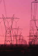
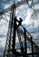
From the moment electricity is generated at a power plant – whether using renewable or non-renewable energy sources – it travels through an extensive transmission and distribution network before reaching consumers.
To transport electricity efficiently, its voltage is first increased using transformers, allowing it to travel over high-voltage transmission lines. It then passes through electrical substations and transformer stations, where the voltage is progressively reduced to levels suitable for distribution and final consumption.
Finally, electricity reaches homes, businesses and industries through the distribution network, where it can be used safely through sockets, lighting circuits and other electrical equipment.
-

Renewable energy sources
The growing electrification of our economy is driving demand for energy sources that will not run out. These are renewable energy sources: natural resources that are either inexhaustible – such as wind, water and sunlight – or can regenerate within a relatively short period, as is the case with biomass.
The main technologies used to harness these natural resources include onshore and offshore wind power, hydroelectric power and solar photovoltaic energy.
-

Non-renewable energy sources
In contrast, technologies that rely on finite resources are known as non-renewable energy sources. These can be divided into two categories: fossil fuels and nuclear energy.
Fossil fuels include oil, natural gas and coal, all of which are widely used to generate electricity. However, they are associated with increased CO₂ emissions and their impact on the climate. In addition, these resources are finite and will eventually be depleted, meaning they cannot meet the world's long-term energy needs indefinitely.
This category also includes nuclear energy, which is considered a low-emissions source of electricity. It works by releasing the energy contained within the nucleus of an atom through the process of nuclear fission, which is the technology currently used commercially, or nuclear fusion, which is still under development and remains at the experimental stage.


How is electricity generated?
There are various sources, which are mainly divided into renewable and non-renewable.
1 Geothermal energy 2 Wind energy onshore 3 Hydroelectric energy 4 Solar photovoltaic energy 5 Wind energy offshore


Non-renewable energy sources
They are polluting and finite

Nuclear energy

Conventional thermal energy (coal, oil and natural gas)
